Key Features
- Powerful 32-bit microcontroller
- 1× Ethernet, 10/100 Mbit/s
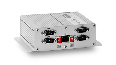
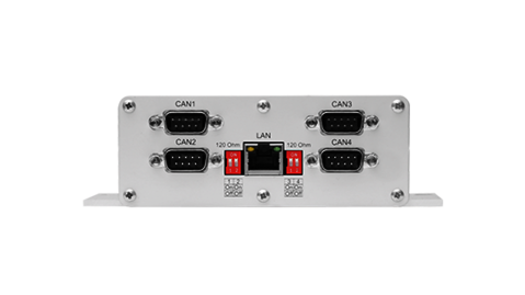
- 4× CAN acc. to ISO 11898, galv. isolated
- Active resistance measurement
- Integrated error frame detection
- Robust aluminium housing
- Including standardized SAE J2534 interface
Description
CAN-to-Ethernet gateway with integrated diagnostic functions
In addition to four galvanically isolated CAN channels, eSys-IDC4E1 provides an Ethernet connection for data transmission to a higher-level computer. For CAN bus monitoring an active resistance measurement is implemented, as well as an error frame detection. With the help of this feature the module is able to take over the troubleshooting in a CAN network. eSys-IDC4E1 has its own logic, which detects error frames and counts them in an internal memory. Thus sporadic errors, such as the falsification of messages by a participant in the network, can be detected.
Standardized SAE J2534 interface
The Sontheim Pass-Thru API is supplied as standard interface with eSys-IDC4E1. Thus the module can be used for applications based on J2534. Other higher level protocols can be easily implemented on request.
Software architecture
The software architecture of the CAN module consists of a host device structure in which an x86 PC system as host uses the module as device to access the CAN bus. Ethernet is used for communication between host and device. Communication is done via IP and a proprietary communication protocol based on UDP. For the identification (discover) of the CAN interfaces via LAN the procedure according to ISO 13400 is used. The firmware of the CAN module consists of a main thread, which processes the CAN communication and is also able to handle the transport layer of communication protocols (e. g. J1939-21/J1939-81, ISO 15765), as well as a diagnostic thread for self- and CAN diagnosis. All services of the module that are not related to direct CAN communication, such as configuration of bridging or CAN diagnostics, are handled via the so-called “toolbox” protocol. The sequence of messages received at the host interface corresponds to the sequence on the physical bus, regardless of whether the message was transmitted or received. This guarantees an extremely high-performance communication with low latency times.
Technical Data
| Hardware | |
|---|---|
| CPU | Freescale PowerPC, 400 MHz |
| RAM | 32 MB (optionally up to 128 MB) |
| Memory | 16 MB (optionally up to 128 MB) |
| CAN | 4× CAN interface acc. to ISO 11898, galv. isolated 2.0 A und 2.0 B |
| Baud rates | 50 Kbit/s up to 1 Mbit/s (incl. 800 Kbit/s) |
| CAN termination resistance measurement | Measurement of the terminating resistor of the CAN bus of the machine; measurement takes place with active bus |
| CAN diagnostic | Error frame detection |
| CAN connections | 4× D-Sub9 |
| LAN | 100 Mbit LAN, RJ45 connection |
| LEDs | LAN Status LED, green and yellow at RJ45 connection |
| Others | Can also be used as CAN-to-CAN bridge |
| CE-Sign | EN 61000-6-2 electromagnetic compatibility (EMC) Interference immunity (10V/m) EN 61000-6-4 electromagnetic compatibility (EMC) Interference emission EN 61000-4-2 immunity to static discharge (ESD) EN 61000-4-3 immunity to radio-frequency electromagnetic fields EN 61000-4-4 immunity against fast transient electrical disturbances EN 61000-4-5 interference immunity against surge voltages EN 61000-4-6 immunity to conducted disturbances induced by high-frequency fields |
| Dimensions (l×w×h) | approx. 121 mm × 151 mm × 48 mm – without connection |
| Housing | Aluminium housing, protection class IP30 |
| Storage temperature | –20°C up to +70°C |
| Operating temperature | 0°C up to +60°C |
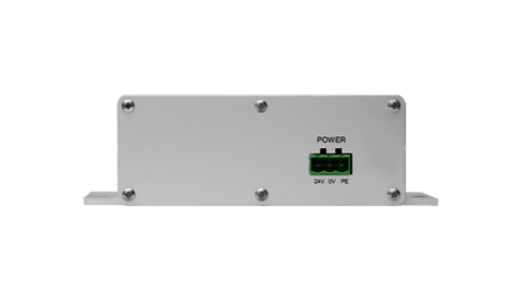
| Supply | 24 V ±10 % / max. 1 A |
Related Products
IoT Device Manager
Cloud based platform for managing your devices in the field
- Management of all IoT-units
- Drag and drop functionality
- Managing over-the-air-updates
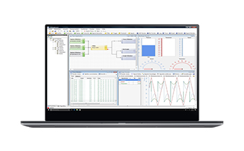
CANexplorer 4
Don’t lose any time during CAN bus diagnostics and benefit from the modular software for acquisition, processing, display and transmission of CAN data.
- Fieldbus analysis tool
- User-defined measurement setups
- Receive, process, send and abstract
- J1939 and CANopen protocol support
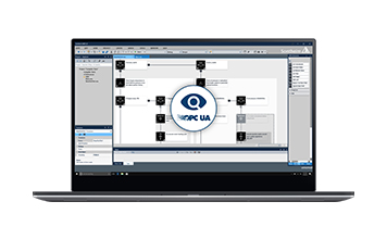
MDT® 2.0 with OPC UA
Next generation modular diagnostic tool for innovative machine park monitoring. Based on OPC UA, ODX and OTX standards.
- OPC UA Server & Client
- ODX 2.2.1 according to ISO 22901-1
- OTX according to ISO 13209
- Multi platform support
